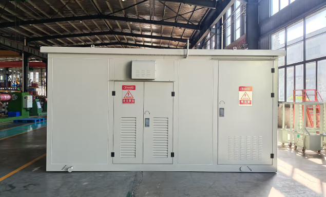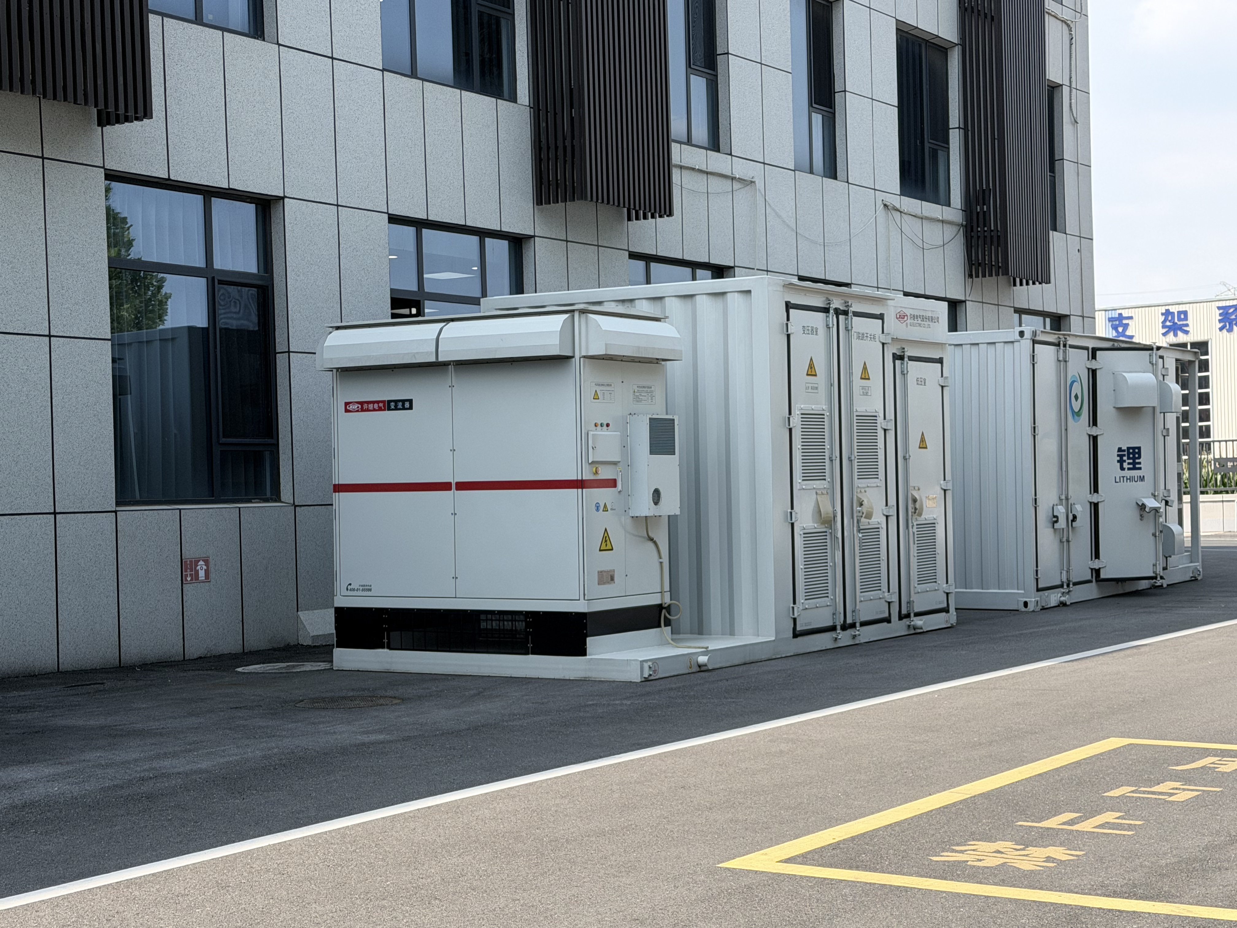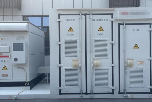
A pre-assembled, all-in-one electrical unit that steps up low-voltage or medium-voltage solar inverter output to higher grid voltages for efficient power transmission.
A solar power compact substation (also known as a photovoltaic prefabricated substation or PV box-type substation) is a factory-assembled, self-contained electrical unit that integrates a step-up transformer, high-voltage switchgear, low-voltage distribution, and ancillary systems within a single weatherproof enclosure. It serves as the critical link between solar arrays and the utility grid, converting the output from solar inverters (typically 0.4–0.69 kV) to medium-voltage levels (10 kV, 35 kV, or 40.5 kV) suitable for grid interconnection.
The compact substation concept has gained significant traction in the solar industry because it addresses several core challenges: space constraints, deployment speed, quality control, and grid-code compliance. By consolidating multiple electrical devices into a single housing, it reduces footprint by up to 70% compared to traditional substations while enabling installation within days rather than months
Solar power compact substations represent a shift from site-built to factory-engineered grid infrastructure. They combine step-up transformation, switchgear protection, and smart monitoring in a transportable enclosure — enabling rapid deployment of utility-scale and distributed solar projects worldwide.
The solar compact substation market is expanding rapidly, driven by renewable energy targets, grid modernization, and the push for faster project deployment.
The global photovoltaic prefabricated substation market was valued at approximately $8.52 billion in 2024, while the broader compact substation market (encompassing all applications) reached $7.8 billion in the same year and is projected to grow to $11.4 billion by 2030 at a CAGR of 6.5%.A separate analysis forecasts the compact substations market growing from $4.69 billion in 2025 to $8.62 billion by 2034 at a CAGR of 6.8%.
In China — the world's largest solar market — the PV prefabricated substation sector is forecast to reach approximately 37.8 billion RMB by 2030, growing at a CAGR of 12.8%. This reflects the country's aggressive renewable energy buildout under its 14th Five-Year Plan and carbon-neutrality commitments.
.png)
The power flow from solar panels through the compact substation to the utility grid.
A solar power compact substation sits between the solar array's inverters and the grid connection point. The DC power generated by solar panels is first converted to AC by inverters at low voltage (typically 0.4–0.69 kV). The compact substation then performs three critical functions: steps up this low voltage to medium or high voltage suitable for grid transmission, protects and isolates the system through switchgear, and distributes and monitors the power flow for grid compliance.
.png)
The enclosure houses all elements in a weatherproof compact metal or composite box, typically rated IP54 or higher, designed to withstand harsh outdoor conditions including temperature extremes, humidity, dust, and salt exposure.
Design PhilosophyThe compact substation follows a modular integration philosophy — each functional compartment (LV, transformer, HV) is physically separated but electrically interconnected within a single transportable enclosure. This enables factory testing of the complete system before delivery to site.
Four primary subsystems work together within the compact enclosure to ensure safe and efficient power conversion.
The step-up transformer is the heart of the compact substation, converting low or medium voltage from solar arrays to higher voltage levels such as 10 kV, 35 kV, or 40.5 kV suitable for grid connection.
Two primary types are used:
Cooling: ONAN (Oil Natural Air Natural)
Voltage: 35 kV / 0.69 kV, with 10/20/33 kV options
Power rating: 500 kVA – 5 MVA typical
Vector group: Dyn11 or Dyn5
Best for: Outdoor solar farms, utility-scale plants
Advantages: Lower losses, stable temperature rise, solar-duty optimized for frequent load fluctuations
Cooling: AN (Air Natural)
Insulation: Class F / Class H
Voltage: 11 kV, 33 kV, 35 kV common
Power rating: 500 kVA – 5 MVA typical
Best for: Refineries, industrial sites, high-safety indoor environments
Advantages: No oil fire risk, environmentally safer, suitable for sensitive locations[
The HV switchgear protects and isolates the system using load-break switches, fuses, or vacuum circuit breakers. It provides critical protection against faults, overloads, and short circuits while enabling safe maintenance isolation.
| Switchgear Type | Function | Typical Use |
|---|---|---|
| Vacuum Circuit Breaker (VCB) | Fault interruption and protection | Primary protection in MV switchgear |
| Load Break Switch (LBS) | Switching under load conditions | Isolation and routine switching |
| SF6 Ring Main Unit (RMU) | Compact MV switching and protection | Optional MV switchgear solution |
The LV distribution compartment manages the incoming current from solar strings or inverters before transformation.
Key elements include:
Space heaters, lighting, ventilation, and earthing terminals ensure safe operation and maintenance access.
The enclosure houses all elements in a weatherproof, compact metal or composite box, often IP54-rated, designed to withstand harsh outdoor conditions.
Typical specifications include:
| Parameter | Specification |
|---|---|
| Enclosure type | Compact / prefabricated outdoor enclosure |
| Typical dimensions | Approx. 15 m × 8 m × 4 m for compact solar packages |
| Protection rating | IP54 standard; IP65 optional |
| Materials | Aluminum, steel, or containerized enclosures |
| Corrosion resistance | Salt spray tested per GB/T 2423.17 |
| Installation | Outdoor or indoor depending on project requirements |
Why compact substations are replacing traditional site-built infrastructure for solar projects.
Solar power compact substations offer decisive advantages over traditional civil-engineered substations in nearly every project dimension — from installation speed to quality control to long-term maintenance.
.png)
From multi-gigawatt solar farms to rooftop commercial installations and solar-storage hybrids.
A1 Utility-Scale Solar FarmsIntegrated step-up transformers, MV switchgear, protection, and control for 10 MW – 500 MW+ plants. Multiple compact substations are deployed across large solar farms to step up voltage for grid transmission.
Refineries, factories, and industrial sites with captive solar plants. Dry-type transformers are often specified for higher safety in industrial environments.
Distributed PV projects on commercial buildings requiring compact grid connection solutions. Smaller ratings (500–2,000 kVA) are typical for rooftop and parking canopy installations.
PV and battery storage integration in the same compact substation platform. This emerging application combines generation step-up with storage interconnection, enabling dispatchable solar power.
For a typical 2,000 kVA solar compact substation, indicative pricing ranges from $16,000–$35,000 (Chinese manufacturers like Jiangsu Subian Electric Power) to $32,000–$58,000 (branded packages from Sungrow / Huawei, which include inverter integration).
Solar compact substations must perform reliably in extreme outdoor conditions — from deserts to coastal environments.
| Parameter | Specification |
|---|---|
| Operating temperature | -40°C to +45°C |
| Maximum altitude | Up to 3,000 m, depending on product |
| Wind resistance | ≤ 30 m/s for outdoor installations |
| Humidity tolerance | Daily ≤ 95%, monthly ≤ 90% |
| Installation site | Safe, non-polluted, non-corrosive, vibration-free |
| Power supply | Near-sinusoidal, balanced three-phase |
| Seismic | Specified by project and product datasheet |
Higher ambient temperatures, high humidity, dust, salt, and extreme cold can affect transformer and switchgear performance. Industrial environments may require dry-type transformers and higher IP protection levels. Coastal or high-salt environments require salt spray testing (GB/T 2423.17) and corrosion-resistant enclosure design.
As solar penetration deepens worldwide, the compact substation will evolve from a passive power conversion unit to an active intelligent grid node. The convergence of power electronics, digital communications, and AI will drive smaller, smarter, and more adaptable substations capable of managing bidirectional flows, integrating storage, and supporting grid stability in ways traditional infrastructure cannot.